Quick Start
This guide walks you through every stage — hardware, firmware, and monitor — so you have a live sensor network running as quickly as possible. For deeper detail on any step, follow the links to the relevant section of the docs.
-
Gather your hardware
A minimal three-node network requires the following components. See the Parts List for exact quantities and purchasing links.
- 3× Heltec WiFi LoRa 32 V3 (~$18 each)
- 1× TMP102 temperature breakout (~$5)
- 1× BMP280 pressure breakout (~$4)
- Jumper wires
- Battery (optional)

-
Install software prerequisites
Install the tools needed for both the firmware and the monitor application before cloning any repositories.
Firmware tools
- PlatformIO — install the PlatformIO IDE extension in VS Code, or run
pip install platformiofor the CLI. - Git — verify with
git --version. On macOS runxcode-select --installif it is missing.
Monitor tools
- Rust —
curl --proto '=https' --tlsv1.2 -sSf https://sh.rustup.rs | sh - Bun —
curl -fsSL https://bun.sh/install | bash - Tauri system dependencies (Linux only):
Terminal window sudo apt update && sudo apt install libwebkit2gtk-4.1-dev build-essential \curl wget file libxdo-dev libssl-dev libayatana-appindicator3-dev librsvg2-dev
Verify everything installed correctly:
Terminal window git --versionrustc --versionbun --version - PlatformIO — install the PlatformIO IDE extension in VS Code, or run
-
Clone and verify the firmware repository
Terminal window git clone https://github.com/AndrewLemons/sensor-net-firmware.gitcd sensor-net-firmwareOpen the folder in VS Code. PlatformIO will automatically detect the project and download the ESP32 board support package. Confirm the toolchain builds cleanly:
Terminal window cd firmware/nodepio runA successful build ends with
SUCCESS. See Firmware Setup for a full project layout reference. -
Assemble the hardware
Wire each sensor breakout to its Heltec board using I2C. The receiver node needs no external wiring.
Temperature node (TMP102)
TMP102 Heltec V3 VCC 3.3V GND GND SDA GPIO 17 SCL GPIO 18 ADD0 GND 
Pressure node (BMP280)
BMP280 Heltec V3 VIN 3.3V GND GND SDA GPIO 17 SCL GPIO 18 SDO GND 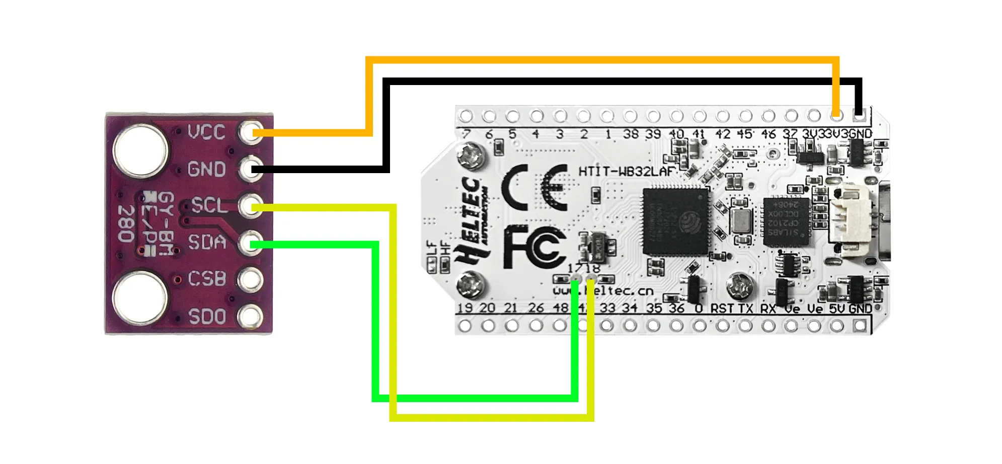
Full wiring diagrams and pin photos are in Hardware Assembly.
-
Configure and flash each node
Open
firmware/node/include/config.hand setNODE_TYPEbefore each flash. Connect the board via USB-C, then run:Terminal window pio run -t uploadFlash all three boards in order:
Node NODE_TYPEvalueSensor attached Receiver NODE_RECEIVERNone Temperature NODE_TEMPERATURETMP102 Pressure NODE_PRESSUREBMP280 After flashing each board, verify the serial output looks correct:
Terminal window pio device monitorThe receiver prints
[REPORT]lines when it hears from sensor nodes. See Building & Flashing for troubleshooting upload failures. -
Clone and set up the monitor application
Terminal window git clone https://github.com/AndrewLemons/sensor-net-monitor.gitcd sensor-net-monitorbun installSee Monitor Setup for a full project layout reference.
-
Run the monitor and connect to the receiver
Start the application in development mode:
Terminal window bun run tauri devOnce the window opens:
- Plug the receiver node into your computer via USB.
- Click the refresh button (circular arrow) to scan for available ports.
- Select the receiver’s port (e.g.
/dev/tty.usbmodemXXXXon macOS). - Click Connect — the baud rate is 115200.
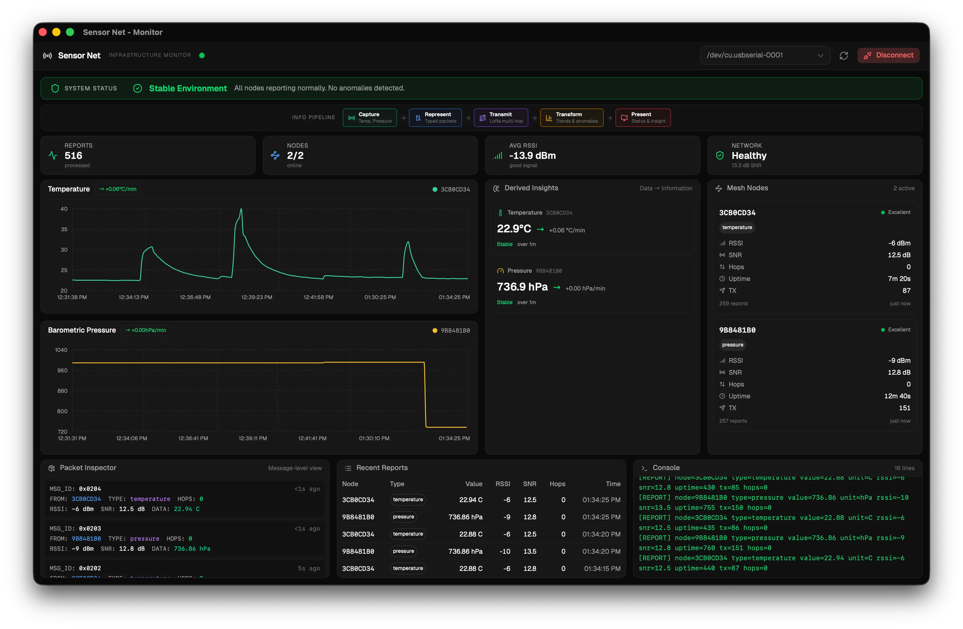
- The status indicator in the header turns green when data is flowing.
Power on all sensor nodes. Within a few seconds you should see live temperature and pressure readings appear on the dashboard.
Next steps
Section titled “Next steps”- Explore the Concepts section to understand how LoRa radio and mesh networking work under the hood.
- Learn how to extend the firmware to add new sensor types.
- Learn how to extend the monitor to add new dashboard panels.
- Review the Configuration Reference for all available build-time settings.