Building and Flashing
This page walks through building the firmware and flashing it to each Heltec board. You will repeat this process for each node in your network, changing the NODE_TYPE in config.h before each flash.
Prerequisites Checklist
Section titled “Prerequisites Checklist”Before you begin, confirm:
- PlatformIO is installed (VS Code extension or CLI).
- The firmware repository is cloned and dependencies are downloaded (see Firmware Setup).
-
config.his set to the desiredNODE_TYPE(see Configuration). - The Heltec board is connected to your computer via USB-C.
Building the Firmware
Section titled “Building the Firmware”Navigate to the firmware project directory and compile:
cd firmware/nodepio runPlatformIO compiles the firmware for the ESP32-S3 target defined in platformio.ini. The first build is slower because the compiler toolchain and all libraries are compiled from source. Subsequent builds only recompile changed files.
If the build succeeds, you will see output ending with something like:
Building .pio/build/heltec_wifi_lora_32_V3/firmware.bin============= [SUCCESS] Took X.XX seconds =============If the build fails, check:
- Is
NODE_TYPEset to a valid value (NODE_RECEIVER,NODE_TEMPERATURE, orNODE_PRESSURE)? - Are all library dependencies downloaded? Try
pio pkg update.
Flashing to the Board
Section titled “Flashing to the Board”With the board connected via USB-C, upload the compiled firmware:
pio run -t uploadPlatformIO automatically detects the connected board’s serial port, puts the ESP32 into bootloader mode, and flashes the firmware. You should see progress output followed by a success message.
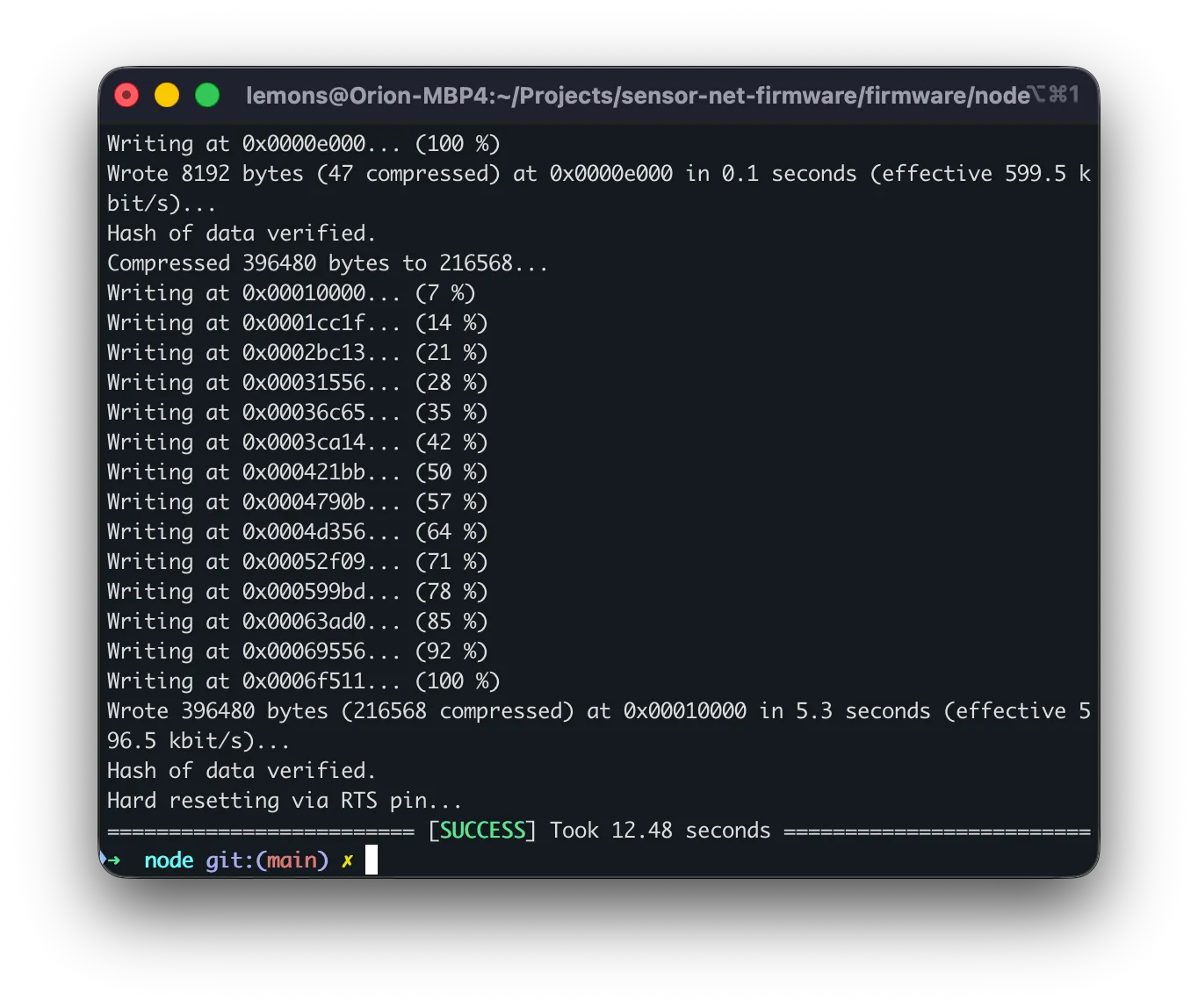
After flashing, the board automatically resets and begins running the new firmware. You should see the OLED display light up with a splash screen showing the node ID and role.

Verifying with the Serial Monitor
Section titled “Verifying with the Serial Monitor”To confirm the node is working, open the serial monitor:
pio device monitorThis connects at 115200 baud (the default for Sensor Net).
Receiver node output:
=== LoRa Receiver Node AABBCCDD ===Firmware 2.0.0  |  Mesh max-hops=3
[RADIO] SX1262 ready
Once sensor nodes are powered on and in range, you will see [REPORT] lines appear.
Sensor node output:
=== LoRa Temperature Node AABBCCDD ===[RADIO] SX1262 ready[SENSOR] TMP102 ready[TX] TMP102=23.45 C #1 (22 bytes)[TX] TMP102=23.50 C #2 (22 bytes)Press Ctrl+C to exit the serial monitor.
Flashing a Complete Network
Section titled “Flashing a Complete Network”For a typical three-node network, follow this sequence:
Step 1: Flash the Receiver
Section titled “Step 1: Flash the Receiver”- Open
config.hand setNODE_TYPE:#define NODE_TYPE NODE_RECEIVER - Connect the first Heltec board via USB.
- Build and flash:
Terminal window pio run -t upload - Verify with the serial monitor that the receiver boots correctly.
- Disconnect this board (or leave it connected if you want to watch reports arrive).
Step 2: Flash the Temperature Node
Section titled “Step 2: Flash the Temperature Node”- Open
config.hand changeNODE_TYPE:#define NODE_TYPE NODE_TEMPERATURE - Connect the second Heltec board (with TMP102 wired) via USB.
- Build and flash:
Terminal window pio run -t upload - Verify that the serial monitor shows
[SENSOR] TMP102 readyand[TX]lines. - Disconnect this board.
Step 3: Flash the Pressure Node
Section titled “Step 3: Flash the Pressure Node”- Open
config.hand changeNODE_TYPE:#define NODE_TYPE NODE_PRESSURE - Connect the third Heltec board (with BMP280 wired) via USB.
- Build and flash:
Terminal window pio run -t upload - Verify that the serial monitor shows pressure readings.
Step 4: Power On and Test
Section titled “Step 4: Power On and Test”- Power all three boards (via USB or battery).
- Connect the receiver board to your computer via USB.
- Open the serial monitor for the receiver:
Terminal window pio device monitor - Within a few seconds,
[REPORT]lines should appear from both the temperature and pressure nodes.
Regenerating Protobuf Files
Section titled “Regenerating Protobuf Files”If you edit proto/messages.proto (for example, to add a new field), you need to regenerate the C bindings before rebuilding:
pip install nanopb./scripts/generate_proto.shThe generated files are placed in firmware/node/lib/proto/. You do not need to run this step unless you have modified the .proto file.
Troubleshooting
Section titled “Troubleshooting”| Problem | Solution |
|---|---|
| Build fails with missing library | Run pio pkg update to download missing packages |
| Upload fails, cannot detect port | Check USB cable (some cables are charge-only). Try a different port. Run pio device list to see available ports. |
| OLED does not turn on | Ensure PIN_VEXT (GPIO 36) is set to OUTPUT and driven LOW in config.h |
| Sensor not detected | Verify wiring (SDA to GPIO 17, SCL to GPIO 18). Check I2C address matches config.h. |
| No reports on receiver | Confirm all nodes use the same radio settings (frequency, bandwidth, SF, sync word). |
Next Step
Section titled “Next Step”Learn how to interpret the serial output in Serial Output.